
 Business License
CCO Wear Plate Applications in Mining: Chutes, Hoppers, and Crusher Liners
An iron ore mine in Western Australia was replacing the discharge chute liners on its primary crusher every 11 weeks. The 12 mm mild steel plates lasted just long enough for the maintenance team to complete one full chute reline before the cycle started again on another section of the circuit. The mine processed roughly 65 million tonnes of ore per year through six crushing stations. Spread across all stations, the annual liner replacement cost — material, labor, and lost production — ran to roughly $2.8 million.
After switching the highest-wear chute sections to CCO wear plate liners, the replacement interval on those zones extended to roughly 14 months, and the annual cost dropped by roughly 41%.
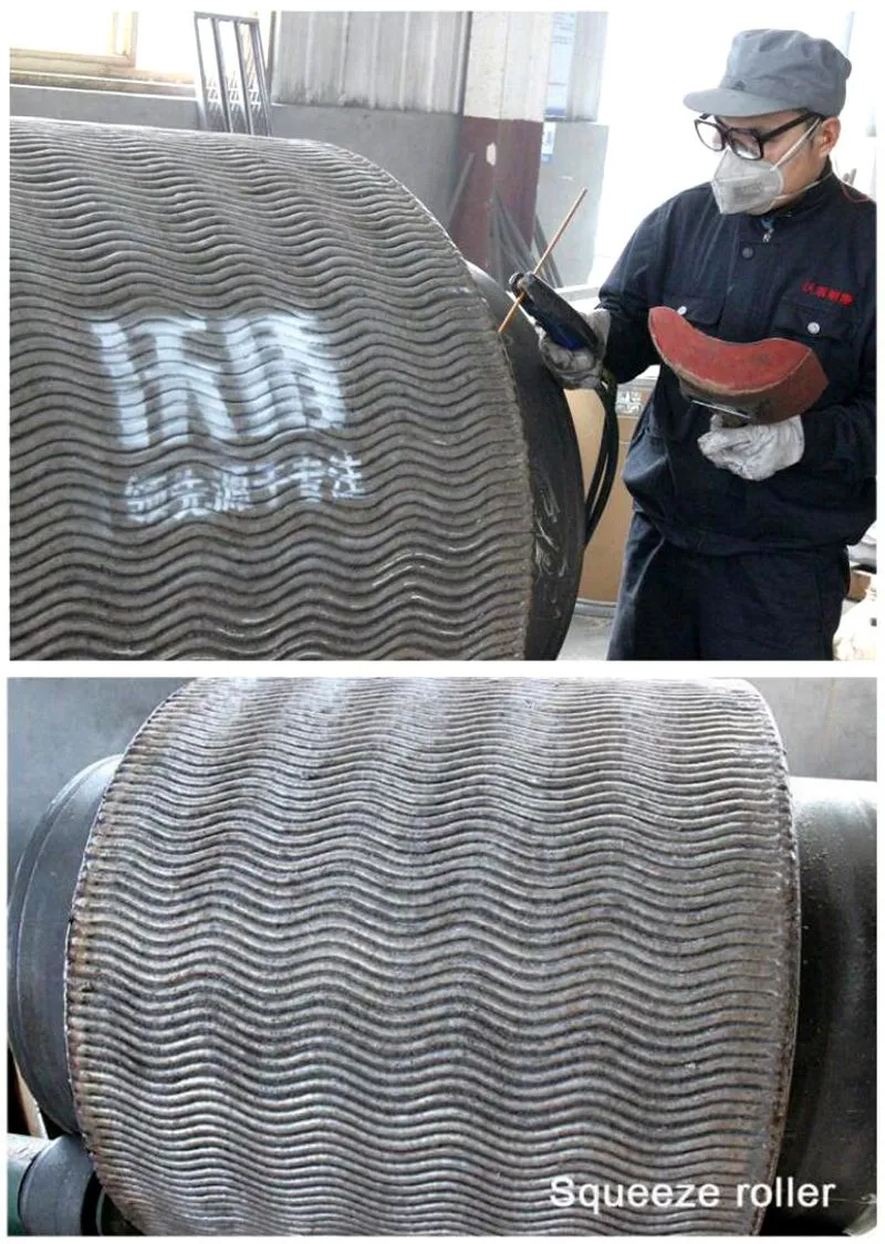
Mining presents the most aggressive wear environment in industrial material handling. The combination of hard, angular rock particles, high throughput rates, and impact loads from falling material creates conditions that overwhelm standard steel liners within weeks or months. Chromium carbide overlay wear plate technology has become the default wear protection solution for a growing share of mining equipment because it provides a thick, metallurgically bonded wear layer that standard steels cannot match. This article examines how CCO plates are applied across the key wear points in a typical mining operation.
1. Why Mining Wear Protection Demands Specialized Materials
Mining wear is dominated by three mechanisms operating simultaneously. Low-stress scratching abrasion occurs when fine ore particles slide across steel surfaces at speed, gradually removing material through micro-cutting and ploughing. High-stress grinding abrasion happens when large rock fragments are crushed between steel surfaces under high contact pressure — the mechanism that destroys crusher jaw plates and gyratory mantle liners. Impact wear results from rocks falling from conveyor discharge pulleys onto chute floors and hopper walls, deforming and fracturing the steel surface.
Standard structural steel grades — Q235, A36, S275 — have a Brinell hardness in the range of roughly 120 to 160 HB. Quartz, the most common hard mineral in ore bodies, has a hardness of roughly 1,100 HV. The hardness ratio between the abrasive and the wearing surface exceeds 7:1, which places the wear firmly in the severe regime.
At this ratio, even abrasion-resistant steels like AR400 (roughly 400 HB) wear at rates that make them uneconomical for high-throughput chute liners. The chromium carbides in a CCO overlay, at roughly 1,400 to 1,800 HV, reverse the hardness ratio — the hard phase in the plate is now harder than the abrasive particles attacking it.
2. Transfer Chutes: The Highest-Wear Zone in the Conveying Circuit
Transfer chutes are where two conveyor belts meet, and the material stream changes direction. A head pulley discharges ore at speeds of 3 to 5 meters per second onto a chute floor or impact plate, often with a drop height of 3 to 10 meters. The combination of velocity, impact, and sliding makes transfer chutes the most wear-intensive components in the mine's material handling system.
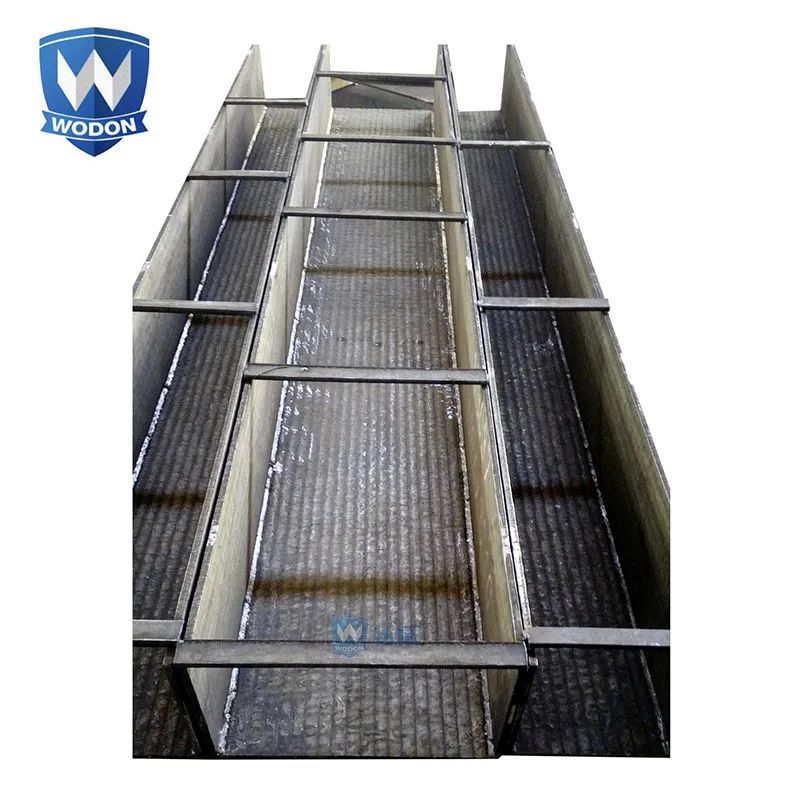
CCO wear plates are applied to three distinct zones within a transfer chute. The impact zone — the area directly beneath the head pulley discharge — takes the full force of falling rock. For this zone, Jiangsu Wodon Wear Resistant New Material Co., Ltd. typically recommends a 10+6 or 10+8 configuration, where the thick base plate resists deformation and the thick overlay absorbs both impact and abrasion.
The sliding zone — the chute floor downstream of the impact point — can use an 8+4 or 8+6 configuration, as impact forces diminish and sliding abrasion becomes the dominant mechanism. The sidewall zone generally experiences lower wear rates and can be protected with 6+4 plates.
Properly specifying the plate configuration for each zone — rather than using the same plate throughout the chute — optimizes the balance between wear life and material cost. The impact zone requires the thickest overlay. The sliding zone benefits from maximum carbide volume fraction for sliding abrasion resistance. The sidewalls need enough overlay to resist occasional rock strikes without adding unnecessary cost.
3. Hoppers and Surge Bins: Managing Abrasion in Storage and Feeding
Hoppers and surge bins store material temporarily and feed it into downstream equipment at a controlled rate. Unlike chutes, where material flows continuously across a surface, hoppers experience a combination of static material pressure, funnel-flow abrasion, and impact from material dropping into an empty or partially filled bin.
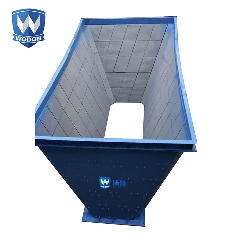
The hopper wall plates experience the highest wear in the flow zone — the lower cone section where material accelerates toward the discharge opening. As the bin empties, the material column above the flow zone exerts pressure on the converging walls, and the sliding velocity of particles against the wall surface increases. CCO plates in this zone are typically 8+4 or 8+6, depending on the ore hardness and the hopper throughput. The upper vertical walls, by contrast, see much lower wear rates and may be adequately protected with 6+3 plates, or even unlined if the ore is soft and non-abrasive.
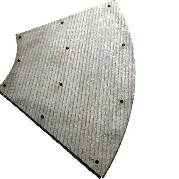
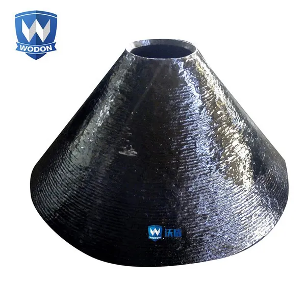
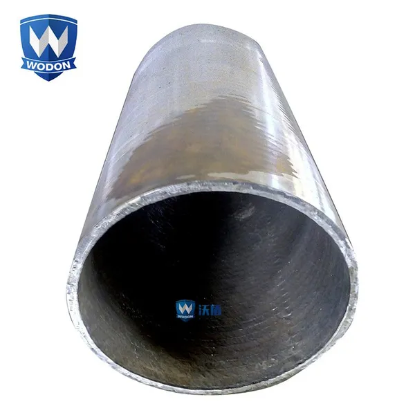
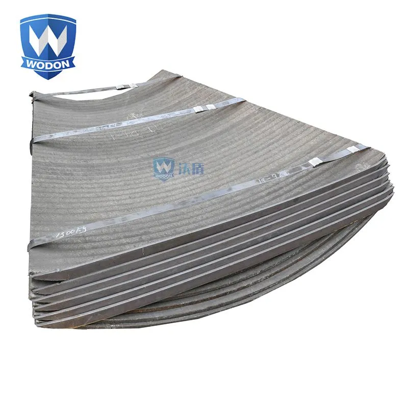
One practical consideration for hopper applications is the installation method. Hopper walls are often curved or conical, requiring the CCO plates to be rolled to match the hopper radius. The rolling process can open existing stress-relief cracks in the overlay if the bend radius is too tight.
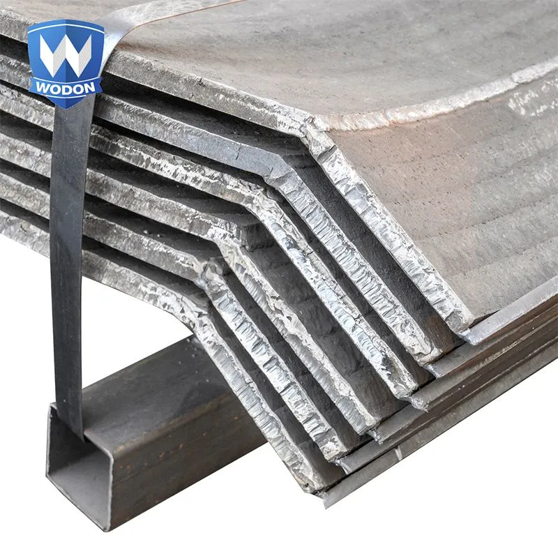
A general guideline is that the bend radius should be at least 10 times the total plate thickness. For a 12 mm plate, the minimum recommended bend radius is roughly 120 mm. Wodon Wear Resistant New Material pre-rolls plates to the specified radius at the factory, eliminating the risk of on-site forming damage.
4. Crusher Liners and Feed Openings
Crushers are the heart of the comminution circuit, and their wear components — jaw plates, mantle liners, and impact bars — are typically made from high-manganese austenitic steel (Hadfield steel) or high-chromium white iron castings. CCO wear plates are not a replacement for these primary crusher wear parts. Their role in crushing circuits is different: protecting the crusher housing and the feed and discharge openings from the abrasive material stream entering and leaving the crusher.
The crusher feed chute — the structure that guides ore into the crushing chamber — is a critical application. Material drops into the feed opening from above, often with significant impact energy. The feed chute liner must absorb impact without cracking and resist the sliding abrasion of ore flowing over its surface into the crusher throat. A 10+6 or 10+8 CCO configuration is typical, with the thick base plate providing the structural integrity to span between support ribs and the overlay delivering the wear surface.
The crusher discharge area, where crushed product exits at high velocity, presents a different wear challenge. The particle size has been reduced, increasing the total surface area of abrasive particles contacting the discharge chute walls. Finer particles tend to slide rather than impact, favoring high carbide volume fraction overlay formulations over impact-tough ones. China Wodon can adjust the overlay chemistry and welding parameters to optimize the microstructure for the specific wear mechanism at each crusher position — higher carbide fraction for the fine-particle discharge stream, tougher matrix for the coarse-particle feed zone.
5. Screen Undersize Pans and Classifying Surfaces
Vibrating screens separate crushed ore into size fractions, and the undersize material — the fines that pass through the screen deck — collects in a pan beneath the screen and flows to a discharge chute. This undersize material is often angular, freshly crushed, and moving at high velocity across the pan surface. The combination makes screen underpans one of the most wear-prone components in the processing plant.
CCO wear plates installed as undersize pan liners must meet two requirements beyond standard abrasion resistance. The plates must be thin enough to avoid adding excessive weight to the vibrating screen assembly — a constraint that limits base plate thickness to 6 mm or 8 mm in most designs. They must also be securely attached to withstand the vibration without loosening.
Plug welding through pre-drilled holes or stitch welding along the edges are the standard attachment methods. Bolted attachments using countersunk bolts are used where the plates need to be replaceable without welding.
6. Selecting the Right CCO Plate Configuration by Mining Application
The table below summarizes the recommended CCO plate configurations for common mining wear points, based on field experience across multiple mine sites and ore types.
| Application | Wear Mechanism | Recommended Plate | Key Consideration |
|---|---|---|---|
| Transfer chute impact zone | Impact + sliding abrasion | 10+8 | Base plate must resist deformation from rock impact |
| Transfer chute sliding zone | High-velocity sliding abrasion | 8+6 | Maximize carbide volume fraction for sliding resistance |
| Chute sidewalls | Low-angle glancing impact | 6+4 | Sufficient wear allowance at lowest material cost |
| Hopper cone section | Pressure + sliding abrasion | 8+6 | Overlay must resist wear under material column pressure |
| Crusher feed chute | Heavy impact + abrasion | 10+8 | Thick base plate for structural integrity |
| Crusher discharge chute | Fine-particle sliding abrasion | 8+6 | High carbide fraction formulation preferred |
| Screen undersize pan | High-velocity sliding abrasion | 6+4 | Weight constraint limits base plate thickness |
| Conveyor transfer point skirt | Sidewall sliding + edge wear | 6+4 | Easy field replacement with bolt-on design |
These recommendations are starting points. Ore hardness, particle size distribution, throughput rate, and moisture content all influence actual wear rates, and a site-specific wear assessment should always inform the final plate specification.
7. Case Examples from Mining Operations
The Western Australian iron ore mine mentioned in the introduction replaced its primary crusher discharge chute impact zone with 10+8 CCO plates after the original 12 mm mild steel liners failed every 11 weeks. The CCO plates were installed in a modular bolt-on configuration, with individual plates weighing roughly 120 kg each — light enough for two technicians to handle without a crane. After 14 months, the impact zone plates showed roughly 2.5 mm of overlay wear in the highest-impact areas.
The sliding zone plates, installed as 8+6, showed roughly 1.1 mm of wear. The maintenance team projected replacement at roughly 20 months for the impact zone and 30+ months for the sliding zone.
A copper mine in Chile converted its SAG mill feed chute from cast manganese steel liners to 10+8 CCO plates. The manganese liners had been work-hardening in service — as expected — but the impact from 150 mm ore lumps was causing spalling at the liner edges where stress concentrated around bolt holes. The CCO plates eliminated the spalling problem because the overlay's crack network absorbed impact energy without producing large, propagating cracks.
8. Frequently Asked Questions
8.1 Can CCO wear plates replace cast manganese steel in crusher components?
CCO plates are not a direct replacement for cast manganese steel in primary crusher wear parts such as jaw plates, cone mantles, or impact bars. Cast manganese steel work-hardens under impact, developing a surface hardness that can exceed 500 HB, and its toughness allows it to deform without fracturing — essential properties for components that experience repeated heavy impact. CCO plates serve a different function in crushing circuits: protecting the crusher housing, feed chutes, and discharge chutes from the abrasive material stream. They complement cast manganese wear parts rather than replacing them.
8.2 How do I determine when to replace CCO chute liners?
Replacement should be triggered by overlay thickness measurement, not by calendar time or visual inspection alone. Ultrasonic thickness gauges calibrated for the overlay material can measure the remaining overlay thickness through the plate surface, typically to an accuracy of ±0.1 mm. A replacement threshold of roughly 1.0 to 1.5 mm of remaining overlay is common — enough wear allowance to schedule the replacement during the next planned shutdown. Waiting until the base plate is exposed risks damage to the chute structure and creates a safety hazard if worn plates detach and enter the material stream.
8.3 Are CCO wear plates suitable for wet, corrosive mining environments?
CCO plates perform well in wet environments where the primary concern is abrasive wear with incidental moisture exposure. However, in highly acidic mine water conditions — common in sulfide ore processing where pH can drop below 3 — the carbon steel base plate can corrode from the back side even while the overlay surface remains intact. For these conditions, specifying a stainless steel base plate (such as 304L or 316L) or applying a protective coating to the back side of the plate can extend service life. The overlay itself is resistant to many chemical environments but is not a corrosion barrier for the base plate.
8.4 What is the recommended attachment method for CCO plates in chutes?
Plug welding through pre-drilled holes in the CCO plate is the most common attachment method for chute liners. Holes are drilled through the plate from the overlay side, and the plate is welded to the chute structure through these holes using a standard mild steel electrode. The weld should be made from the overlay side ensuring penetration into the chute structure.
For applications requiring frequent replacement, bolt-on designs with countersunk bolt heads below the overlay surface allow fast change-out without welding. Stud welding — welding threaded studs to the back of the plate before installation — is a third option that combines the security of welded attachment with the replaceability of a bolted connection.
Recently Posted
-
How to Choose the Right Chromium Carbide Overlay Wear Plate: A Procurement Guide
August 11, 2026A cement plant in North Africa ordered 120 square meters of chromium carbide overlay wear plate for a clinker conveyor chute rebui Read More
 -
CCO Wear Plate vs. Hard Chrome Plating: Comparing Wear Protection Methods
August 10, 2026A hydraulic cylinder manufacturer in Germany faced a recurring warranty claim: the chrome-plated piston rods on their mining excav Read More
 -
Chromium Carbide Overlay Wear Plate: What It Is and How It Works
August 7, 2026A copper mine in South America was losing roughly 14 days of production every quarter. The culprit was not the ore body or the pro Read More
 -
Wodon Bimetallic Wear-Resistant Steel Plates: Engineered for Superior Performance and Longevity
January 3, 2025In the demanding landscape of heavy industries, where abrasion, impact, and corrosion are constant adversaries, Wodon Bimetallic W Read More

Contact Us
Recommended Products
-
 Chromium Carbide Overlay Wear Plate WD-1900 Smooth Surface CCO Wear PlateNegotiableMOQ: 1 Square Meter
 -
Hardfacing Wear Resistant Flux Cored Welding Wire With High HardnessNegotiableMOQ: 1 Kilogram
-
High Abrasion Resistant Hardfacing Wear Liners Chromium Carbide Overlay Cco Bimetallic Wear PlateNegotiableMOQ: 1 Square Meter
-
Chrome Carbide Wear Resisting Plate High Wear Steel Plate Wear Liner Platebimetallic Wearable Lining Plate Bucket ExcavatorCHF 300 - 300MOQ: 1 Square Meter
-
Wodon Customizable Steel Flux Cored Welding Wire Manufacturer's Valve Surfacing Gas Shielding OEM SupportUS$ 4.02 - 4.02MOQ: 1 Kilogram
-
Abrasive Resistence Wear Parts Overlay Carbon Chromium Steel PlateNegotiableMOQ: 1 Square Meter
-
Wear Plates for Heavy Duty Mining Applications High Chromium Carbide Overlay Abrasion Resistant and Customizable SizesNegotiableMOQ: 1 Square Meter
-
Hardfacing Truck Liner Plate Chromium Carbide Overlay Wear Plate Cladded PlateNegotiableMOQ: 1 Square Meter
-
Custom Overlaying Wear Plate - Economical Choice for Durable Industrial Applications, High-Quality Fabrication, 55HRC HardnessNegotiableMOQ: 1 Square Meter
-
Wear Abrasion Resistant Overlay High Carbon High Chromium Steel PlateNegotiableMOQ: 1 Square Meter
-
Wear Resistant Steel Plate 6mm 8mm 12mm Thickness Hot Rolled Carbon Steel Plate Wear PlateNegotiableMOQ: 1 Square Meter
-
Bimetallic Cco Clad Composite Overlay Hardfacing Wear Resistant Steel PlateNegotiableMOQ: 1 Square Meter
-
High-Performance Wear Plates for Cement Mills Chromium Carbide Overlay Long Service Life Reliable PerformanceNegotiableMOQ: 1 Square Meter
-
Wear Resistant Steel Plate Liners for Chutes Special Use Wear LinersNegotiableMOQ: 1 Square Meter
-
Cco Hardfacing Surfacing Tungsten Carbide Wear Resistant Plates Liner for SilosNegotiableMOQ: 1 Square Meter
-
Wodon Chromium Alloy Bimetal Hardfacing Plate for Mining MachineryCHF 300 - 300MOQ: 1 Square Meter
-
Hardfacing Abrasion High Wear Resistant Performance Cladding Plate TubeUS$ 399.69 - 399.69MOQ: 1 Square Meter
-
Hardfacing Plates for Manufacture Industry Value High Chrome Wear PlateUS$ 100 - 300MOQ: 1 Square Meter
-
Customizable OEM/ODM Wear-Resistant Soldering & Surfacing Flux Cored Welding WiresUS$ 9.9 - 9.9MOQ: 1 Kilogram
-
Chromium Carbide Round Pipe 6m and 12m Lengths Bending & Cutting Services Welding Technique Saw TechniqueUS$ 6 - 6MOQ: 1 Square Meter